

Integrated PLC & SCADA.
One Engineering Platform.
Mitsubishi Adroit Process Suite (MAPS) is an integrated PLC and SCADA engineering and life-cycle management solution that brings control, visualisation, reusable engineering libraries, diagnostics and project information together in one structured automation environment.
Engineer Once. Standardise the Entire Automation Life Cycle
Mitsubishi Adroit Process Suite (MAPS) is an integrated PLC and SCADA programming and management solution developed through collaboration between Adroit Technologies and Mitsubishi Electric Factory Automation. Unlike conventional projects where PLC logic, SCADA tags, graphics, alarms and documentation are often engineered separately, MAPS uses preconfigured and tested engineering libraries to bring these disciplines together in one structured environment.
Reusable equipment objects can combine PLC function blocks with the corresponding SCADA tags, scanning, alarming, logging, auditing and visualisation, while bulk engineering tools, wizards and templates reduce repetitive configuration. MAPS also supports simulation for testing and commissioning, built-in diagnostics and maintenance tools, automatic project reporting and documentation, open connectivity and scalable client-server architectures.
The result is a standards-based life-cycle engineering platform designed to improve consistency, reduce engineering and commissioning effort, simplify maintenance and keep PLC and SCADA functionality aligned from specification through operation.
What MAPS Does
Features and Benefits
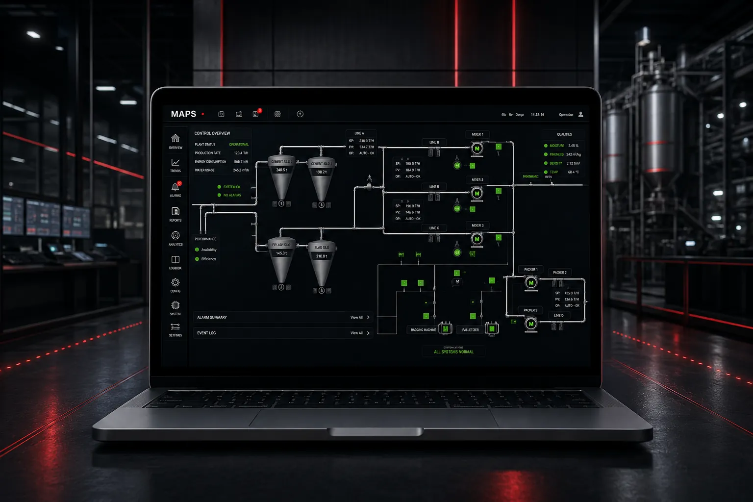
Engineer PLC control and SCADA visualisation as one coordinated solution, using common engineering standards and reusable equipment definitions across the project.
Benefit: Reduces duplication between PLC and SCADA engineering and helps keep control logic, visualisation and operational behaviour aligned.
Use preconfigured and tested engineering libraries containing standard equipment objects, graphics, wizards and templates for common industrial devices and functions.
Benefit: Gives engineers a proven starting point, reducing repetitive work and improving consistency between projects.
Use a structured single point of configuration together with bulk engineering methods, including Excel-based tag configuration and automated project-data generation.
Benefit: Reduces manual entry and repeated configuration, making larger projects faster to engineer, review and maintain.
Create standard equipment objects for devices such as motors, VSDs and valves that can generate associated PLC function blocks together with SCADA tags, scanning, alarming, logging and auditing.
Benefit: Speeds up engineering while ensuring each equipment item is implemented consistently across PLC and SCADA.
Build operator interfaces using enhanced graphic libraries, vector-based graphics, standard controls, reusable shapes, wizards and templates.
Benefit: Improves engineering productivity and makes it easier to deliver consistent operator interfaces across the plant.
Use simulation functionality available on common MAPS equipment objects to test configured behaviour before the physical instrumentation is connected.
Benefit: Allows more of the solution to be validated before live commissioning, reducing onsite fault-finding, time and project risk.
Generate and retain project information such as I/O schedules, configuration reports, functional design information, backups and supporting documentation throughout the system life cycle.
Benefit: Improves handover quality and helps keep engineering documentation aligned with the implemented automation solution.
Connect MAPS to industrial devices, databases and external applications through an open client-server architecture with extensive protocol and data-interface support.
Benefit: Allows MAPS to integrate into mixed-vendor environments and scale from stand-alone applications to distributed systems.
Use Windows-based users and groups to control access, while built-in auditing records engineering, system and setpoint changes for traceability.
Benefit: Protects engineering and operational functions while providing a clearer record of changes made to the system.
Use SNMP network-management capability and demand-based scanning so data required for display, logging, alarming or calculation can be handled efficiently.
Benefit: Supports better visibility of industrial-network health while reducing unnecessary PLC and network communications.

Technology Stack & Data Flow
How MAPS Works
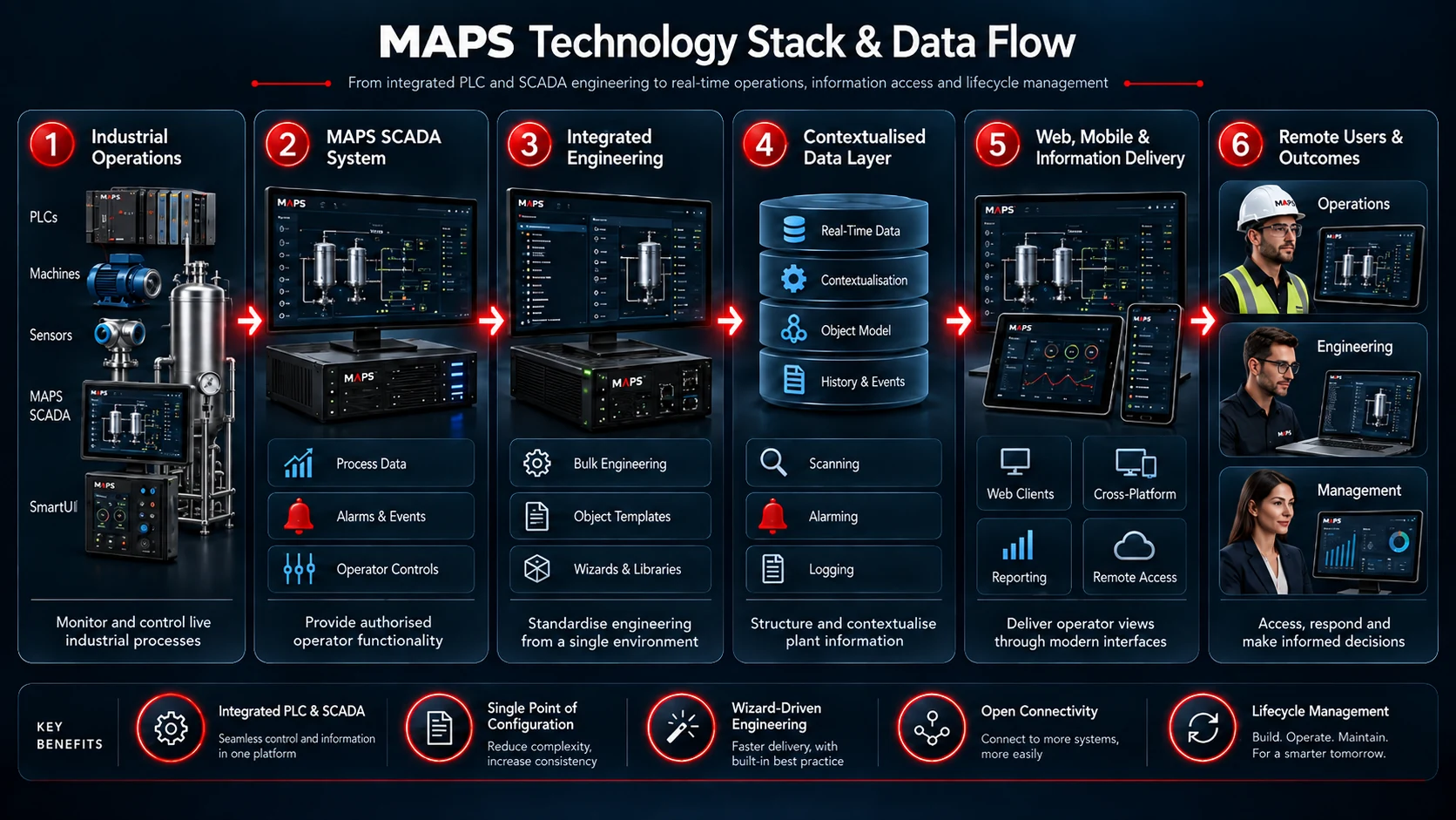
MAPS connects field devices and PLC control with real-time SCADA data, reusable engineering objects, visualisation and wider information systems so the same standards can support the automation project from engineering through operation and maintenance.
Connect Field Devices and PLCs
Connect Mitsubishi Electric Factory Automation MELSEC PLCs and supported third-party controllers, instruments and IT devices through MAPS protocol drivers and open industrial communications.
Acquire and Process Real-Time Data
The MAPS Agent Server provides the real-time data layer for scanning, alarming, data logging and intelligent Agents, with additional functions such as Alarm Management, OEE, Max Demand, IoT and network monitoring available where required.
Engineer and Visualise
Use the MAPS Designer, reusable equipment-object libraries, wizards and templates to configure standardised PLC and SCADA functionality, then present live process information through SmartUI / Operator graphic forms.
Integrate Information and Extend Access
Exchange operational information with databases, reporting, web services, OPC UA, MQTT and external applications, with authorised remote or mobile access available through related Adroit product suite mobility solutions where required.
A Closer Look at MAPS
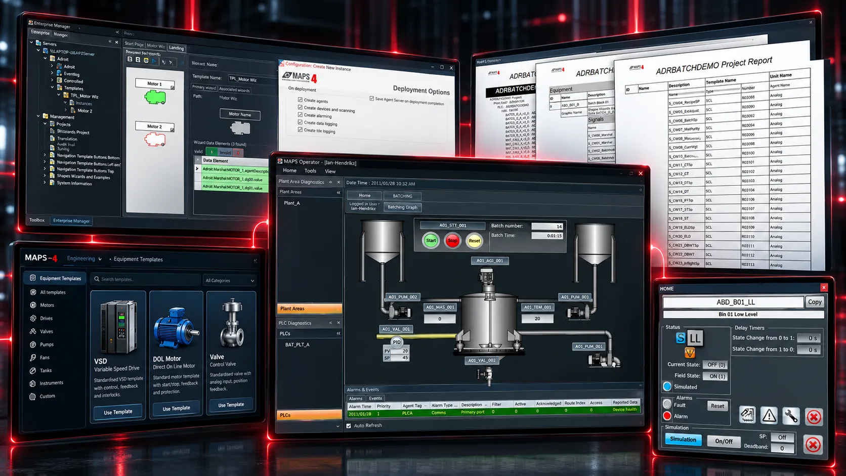
Explore how MAPS standardises engineering, automatically creates connected PLC and SCADA functionality, supports testing before commissioning and keeps project information available throughout the automation life cycle.
Equipment Objects and Auto-Configuration
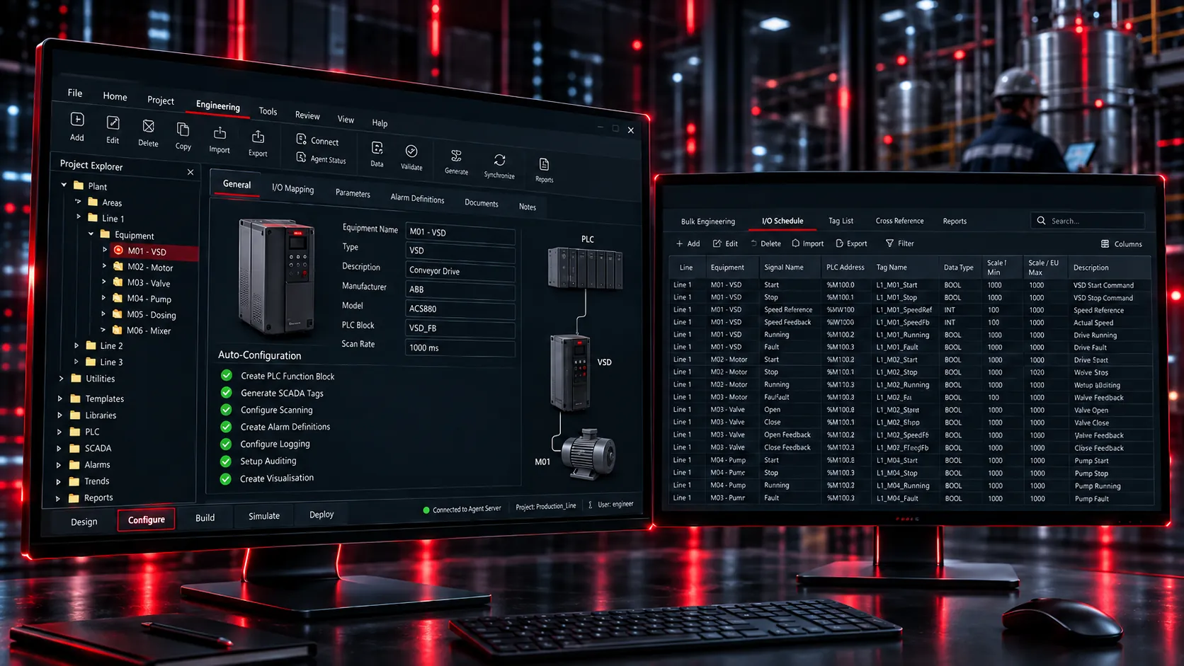
A standard equipment object such as a VSD, DOL motor or valve can create the corresponding PLC function block together with SCADA tags, scanning, alarming, logging, auditing and visualisation.
Bulk Engineering and I/O Schedules
The Excel-based bulk-engineering workflow, together with generated I/O schedules and configuration reports, reduces repetitive configuration and supports consistent project data.
Simulation, FAT and Commissioning
MAPS equipment objects and faceplates can operate in simulation mode, so configured behaviour can be tested before the physical instrumentation is connected.
Life-Cycle Documentation and Diagnostics
MAPS links the live automation project and its diagnostics with engineering deliverables such as functional design information, I/O schedules, SOPs and backups, supporting the system beyond commissioning.
One Integrated View of Your Automation Environment
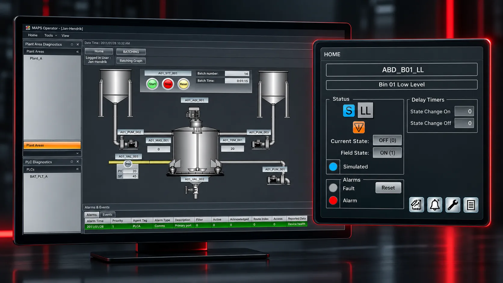
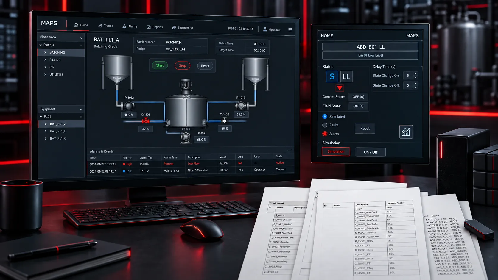
MAPS brings process visualisation, control, engineering and operational information together in a single integrated environment. Operators can monitor plant conditions and respond to process events, while engineering teams work with the same underlying automation structure to configure, maintain and improve the system.


Questions often asked.
MAPS is an integrated PLC and SCADA engineering and life-cycle management solution that brings control, visualisation, reusable engineering libraries, diagnostics and project information together in one structured automation environment.
In a conventional project, PLC logic, SCADA tags, graphics, alarming and documentation may be engineered separately. MAPS uses reusable equipment objects and tested libraries so related PLC and SCADA functionality can be configured as a coordinated solution.
MAPS equipment objects can combine the PLC function block with the corresponding SCADA tags, scanning, alarming, logging, auditing and graphic behaviour, creating a common engineering approach across both parts of the automation solution.
The supplied MAPS material identifies compatibility with Mitsubishi Electric Factory Automation MELSEC iQ-R, iQ-F and Q-Series PLC platforms. Hardware and engineering-software requirements should be selected to suit the project architecture and I/O requirements.
Yes. MAPS uses an open client-server architecture with extensive industrial protocol and data-interface support, including technologies such as OPC UA, MQTT, BACnet, Modbus, web services and database connectivity.
Equipment objects are reusable, preconfigured building blocks for common plant equipment. They can package PLC control logic, SCADA configuration, graphics and related functions so the same standard can be instantiated consistently throughout a project.
MAPS reduces repetitive work through tested libraries, reusable objects, automatic creation of related PLC and SCADA elements, bulk configuration, generated I/O schedules and standardised engineering workflows.
Yes. Common MAPS equipment objects include simulation capability that can be used to test configured behaviour before live instrumentation is connected, supporting Factory Acceptance Testing, Site Acceptance Testing and commissioning.
MAPS uses Windows-based user and group security, provides built-in auditing for engineering, system and setpoint changes, and supports life-cycle documentation such as functional design information, I/O schedules, project backups and supporting documents.
Yes. The MAPS architecture supports stand-alone, centralised, distributed and clustered configurations, allowing the solution to be applied from smaller systems through to larger multi-server and distributed installations.
One Standard. PLC to SCADA.
Talk to us about standardising your next automation project with MAPS, from engineering and commissioning through to operation and maintenance.